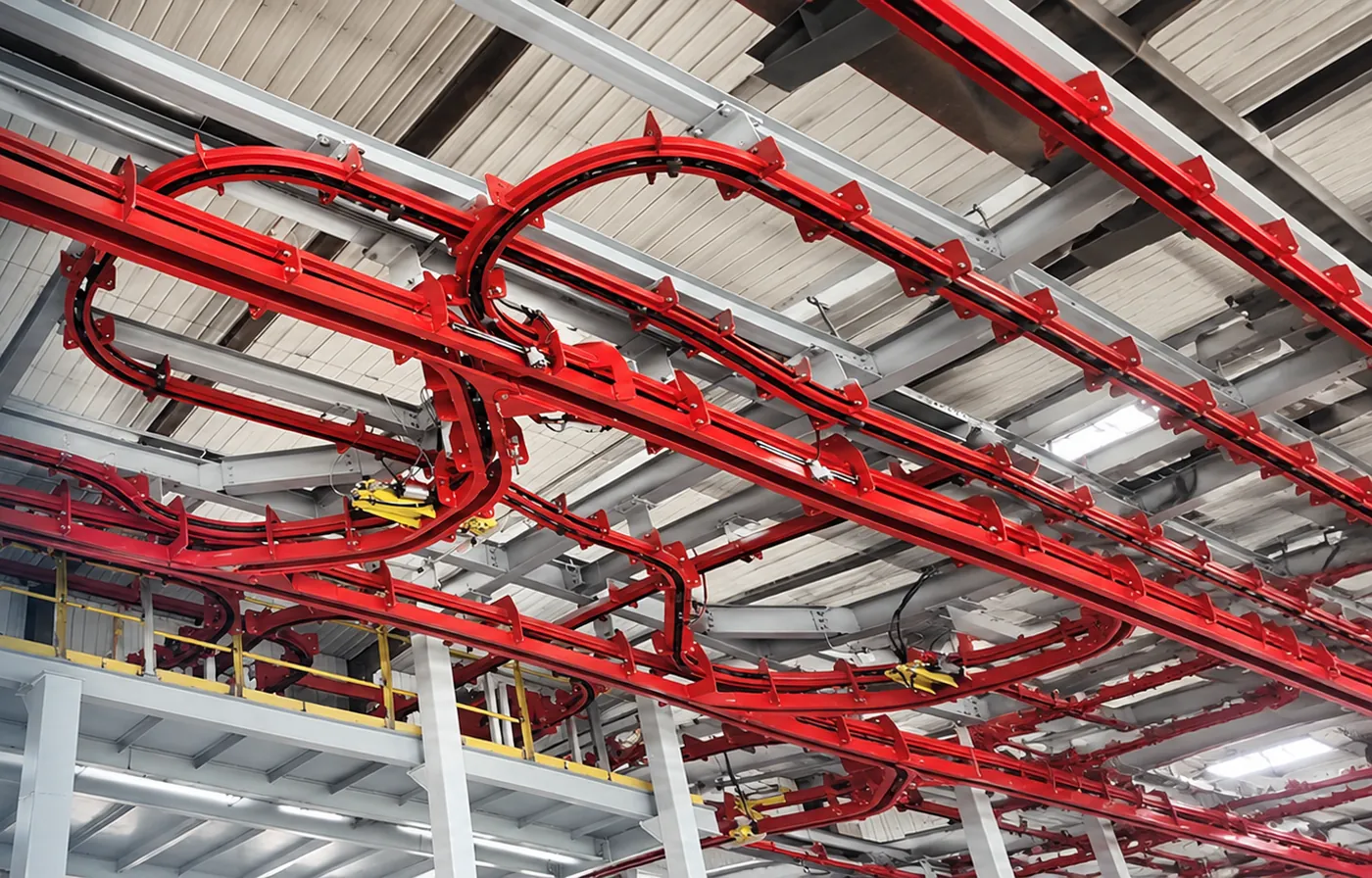
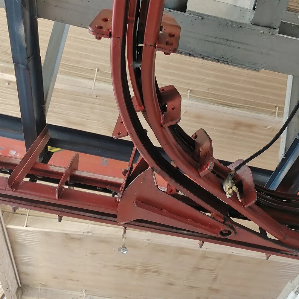
Power and free conveyors give designers many options: main loops, branches, parallel stations, storage lanes and repair loops. The layout decides how well these options serve your process.
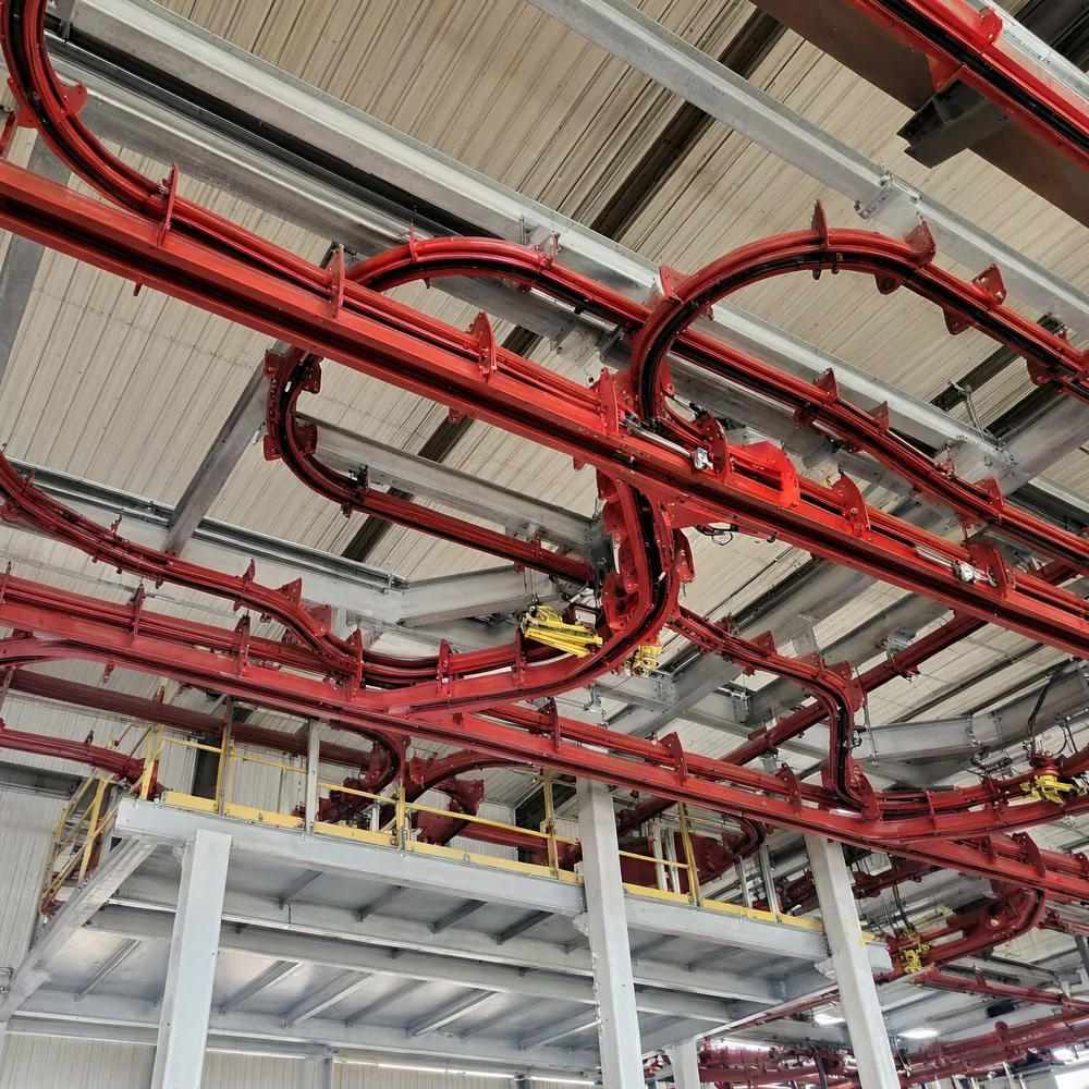
Layout building blocks
| Element | Purpose |
|---|---|
| Main loop | Carries carriers through the core processes and back |
| Branch | Takes carriers to a station, process or area and back |
| Parallel stations | Several stations sharing work at a bottleneck |
| Storage lanes | Buffers for batching, colour sorting or sequencing |
| Repair loop | Takes defective products out and back into flow |
| Empty carrier return | Brings carriers back to loading, often with an empty buffer |
| Maintenance spur | A side track where carriers can be removed for service |
Step-by-step layout design
- Map the process: list every station, its cycle time and position in the building.
- Calculate the flow: takt time, carrier pitch and chain speed; see the layout planning guide.
- Draw the main loop: the shortest route through the core processes.
- Add branches and parallel stations where cycle times exceed the takt.
- Size buffers: number of carriers per lane from the stoppages to bridge.
- Place switches, stops and identification points with enough distance for decisions.
- Place drives and take-ups from the chain pull calculation.
- Check clearances in curves, vertical curves and at building crossings.
Sizing storage lanes
Lane length ≈ carriers in lane × accumulated carrier length
Example: a lane holding 12 carriers with an accumulated length of 1.5 m each needs about 18 m of track, plus the switch, stop and entry zones. Try the numbers in the sizing calculator in our price and cost guide.
Drives and take-ups
Each chain loop needs at least one drive and one take-up. The take-up is usually placed just after the drive, where chain tension is lowest. Long loops may need several drives that share the load. Keep drives and take-ups out of ovens and wet zones and reachable for maintenance.
Common layout mistakes
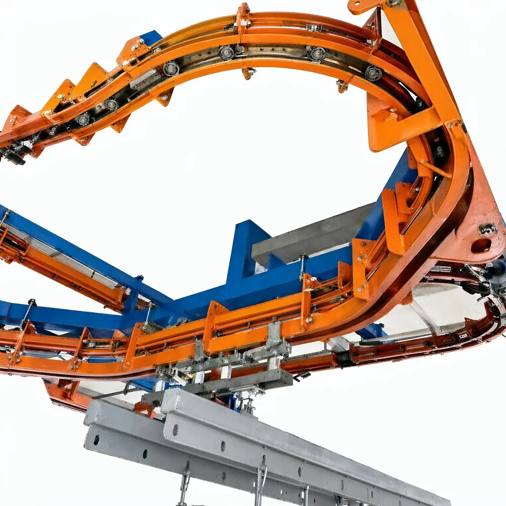
- Buffers sized by guess instead of stoppage data
- Identification points too close to switches
- Merges without stops, so carriers block the main line
- Vertical curves right before stations or stops
- No space reserved for future lanes or stations
- No maintenance spur, so carriers cannot be removed without stopping the line
See also power and free conveyor switches and send us your layout for a review by HITREE engineers.
Worked example: adding parallel stations
A line runs at a takt of 90 seconds, but the masking station needs 160 seconds per carrier. One station cannot keep up. A branch with two parallel masking stations gives each station 180 seconds per carrier, enough for the work plus a margin. A diverting switch alternates carriers between the two stations, and a merging switch with a stop brings them back to the main line.
Questions to ask about a power and free layout
- How were takt time, chain speed and pitch calculated?
- How were buffer sizes derived, and from which stoppage data?
- Has the layout been checked with a flow simulation?
- Where can the layout be extended in future?
- How are carriers removed for maintenance?